A gas (BF3, AsH3, PH3) is introduced between a metal plate and a hot filament
A potential is applied between the filament and plate (filament negative, plate positive)
Electrons boil off the filament and are accelerated toward the plate
Plasma is created by collisions between high-energy electrons and gas molecules
A magnetic field is created also in parralel to improve plasma efficiency, by increasing the electrons path
Extraction assembly - extracts the positive ions
Ions are attracted by an electrode with large negative potential
The beam is made smaller by a slit
Magnet - separates the ions with the suitable mass
It is neccessary to separate the ions, beacuse in a plasma a lot of ions are created with various mass (for example from BF3: BF2+, BF3+, BF+, B+), and these ions will have various momentum, therefore will be implanted at various depths in the wafer (which is not desired)
The magnet curves the charged particles trajectory
The neutral atoms will move in a straight line, unifluenced by the magnet
The heavy ions (green and yellow in the animation) and the lighter ions (blue) will be deflected from the ion beam, into the walls
Only the ions with the suitable mass will continue their journey to the wafers, through the narrow slit
Graphite walls are used to absorb the ions energy, avoiding heating
Knowing the mass of the desired ions, the radius of the system can be calculated as a function of the ion velocity: , where:
r - radius
B - magnetic field
m - ion mass
Vext - acceleration voltage
q - ion charge
Acceleration column - accelerates the ions
can be placed before or after the magnet (if it is before, then a much larger magnet is needed, due to higher velocities)
sometimes the column is placed between two magnets, both have the same purpose of mass analyser and separator
it is several meters long, in order to reach the high speed required for implantation
consists of a set of rings, on the first 20 V are applied, on the second 40, third 60, and so on
Process chamber - ions collide with the wafer surface
the disk with wafers is scanned and rotated in front of the ion beam
the beam is also rastered across the wafer with the help of deflection plates (a low rf potential is applied on the plates the modify the beam orientation; X-axis and Y-axis deflection plates)
the beam is bended to avoid neutrals implanting in the center of the wafer
the implantation dose (Q) is calculated with the help of a Faraday cup placed behind the wafer and connected to the ground (it collects the charges that pass through a slit in the disk and the current is measured)
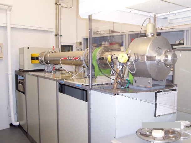
In the picture, the acceleration column can be seen. The pressure chamber is in the front side. The mass analyser and ion source are in a room in the back and cannot be seen.

 Substrate preparation

 , where: