IPCI logo
Internet-based Performance Centred Instruction
Electromechanical Transducers tutorial

Modules

1. Electrostatic Transducers
2. Piezoresistive Transducers

pages: 1 2 3 4 5 6 | next

Fundamentals of piezoresistive conversion

  • Dependence of electrical resistivity on strain and consequently on stress
  • Can be used only as a sensor
  • Strains change the internal atom positions and their motions and hence, the resistivity
  • First strain gauges based on the piezoresistive effect consisted of metal wires on a paper carrier
  • Semiconductors show a much greater piezoresistive effect

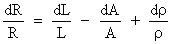
Basic resistivity relationships

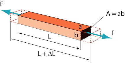
Case of a long solid bar

      • When a load, F is applied, the object deforms, causing the resistance change
      • Resistance, R of the bar

where L is the length, A is the cross-section and r is the resistivity of the material

      • Relative resistance change
        Differentiating the preceding equation:

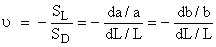
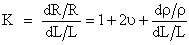
Two components of the piezoresistive effect

  • Geometric component
  • Resistive component

      • Relative resistance change

With the aid of Poisson ratio, n

defined as the relative increase in the length SL to the relative decrease in the diameter SD (or a or b)

      • Gauge factor K

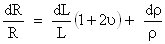
In metals, the gauge factor is defined mostly by the geometric component

which is expressed by two first members of the preceding expression

For this reason, the gauge factors of metals are rather small and attain the values between 2 and 4.

Gauge factor of semiconductors is much higher

Doped silicon exhibits a gauge factor which can be as large as 200, depending on the amount of doping

This effect is the result of the resistive component corresponding to the third member of the preceding expression

1. Electrostatic Transducers
2. Piezoresistive Transducers

pages: 1 2 3 4 5 6 | next

go to top