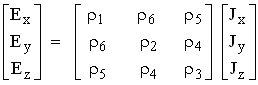
Resistivity in an anisotropic material defined as a relation the electric field, E to the current flow, J
E and J in 3-dimensions
Resistivity, r defined as a second-rank tensor that has nine elements expressed in a 3׳ matrix
These elements reduce to six independent values from symmetry considerations
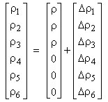
Case of silicon crystal aligned to the (100) axes Cubic lattice structure Entries ρ1, ρ2 and ρ3 will be equal, as they all represent resistance along the (100) axes (denoted by ρ) Remaining components represent cross-axis resistivities, will be zero because unstressed silicon is electrically isotropic
When stress is applied to silicon, the components in the resistivity matrix change:
Matrix of relative resistivity d: where Dr ... resistivity variation
r ... unstrained resistivity
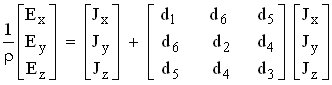
Electric field - current relation in more general form:
Relative resistivity
Related to the stress by the piezoresistive effect
Stress and resistivity are a second-rank tensors
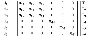
Piezoresistive effect requires a four-rank tensor of piezoresistive coefficients for its full description
Due to symmetry conditions, this tensor is populated by only three non-zero components, as shown:
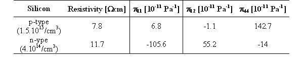
Piezoresistive tensor coefficients, πij have units of Pa-1
They may be either positive or negative and are sensitive to doping type, doping level and operating temperature
π11 relates the resistivity in any direction to stress in the same direction
π12 and π44 are cross-terms
Typical room-temperature values of piezoresistance coefficients and resistivity for p-type and n-type silicon:
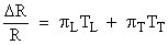
Relative resistance change Preferred representation expressing the fractional change in an arbitrarily oriented diffused resistor
Where
πL and TLare the piezoresistive coefficient and stress parallel to the direction of current flow in the resistor (i.e., parallel to its length)
πTand TTare the values in the transverse direction
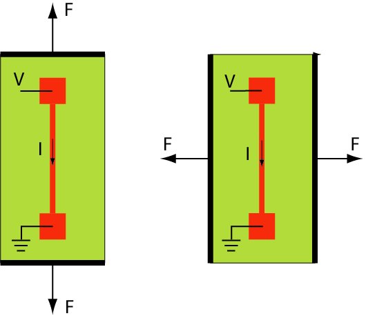
Orientations of piezoresistor relatively to the applied stress correspond to the most common situations in piezoresistive sensor devices
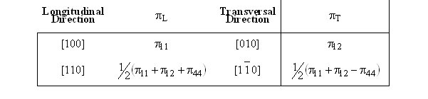
Longitudinal orientation
Transversal orientation
Piezoresistive coefficients for two possible gauge orientations in the case of (100) silicon wafers

 Accelerometer