 |
|
||
|
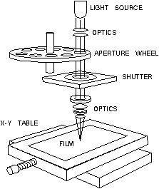
Photo-plotter Post –processing formats which are valid for driving a photo-plotter are as follows: · Artwork; · Drill drawing; · Power and ground plane; The photo-plotter is used for placing all lines, pads, copper areas with right form and dimension as were created in the CAD system. Below a schematic view of a photo-plotter is presented.
Before diving into the details of the photoplot file a short discussion of photoplotters will make the following material easier to digest. Early photoplotters consisted of a precision servo controlled X-Y table to which a piece of high contrast film is attached. A bright light source is directed through a shutter, through an aperture wheel and focused onto the film. A controller converts Gerber commands into the appropriate table movements, wheel rotation and shutter opening.
Schematic view of a photo-plotter
Plotted items are interpreted as apertures. A photo-plotter is just the name implies: a plotter that writes using light. The "writing" tool is a optical exposure head having a shutter and a specific aperture. In order to perform the job, a plotter has to be told: 1. Which aperture (tool) to use. 2. When to use the aperture and when not to. 3. Where to go next. 4. If to go there in a straight line or along an arc.
|
 Schematic design of PCB projects

