Design a PCB analog module which supervise the AC power supply voltage of mains and indicate based on 3 LEDs (one red LED for over-voltage, one red LED for under-voltage and one green LED for OK-working) if the voltage is into the correct range (210...250V). The current of LEDs shall be of 10mA. Use comparators/operational amplifiers in an optimim number and packaging and try to find a solution for the DC power supply of integrated circuits in order to use no transformer.
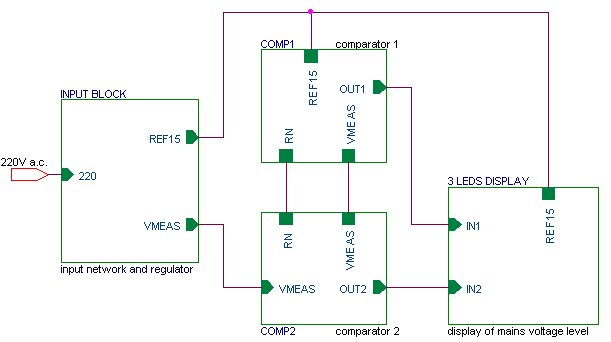
Remark: For 'beginner' level in PCB design, the tutor can offer to student the schematic diagram of the task.
Requirements for the printed circuit board:
- Single-layer PCB (bottom side);
- More than 50% of components as SMDs, inclusive the comparators (SOIC is preferred);
- PCB tracks: min. 0.5mm, rounded corners;
- Spacings: min. 0.5mm;
- AC power supply voltage bars: min. 2mm;
- DC power supply of integrated circuits: 15V, PCB tracks of 0.8mm;
- Board: rectangular in shape, with 4 mounting holes of 3.2mm at corners;
- Components density (Area of components/Area of board) > 40%.
The task consists in the conception and design of the analog PCB module presented above and understanding of design techniques for development of a single-layer printed circuit board for analog applications.
The task has to be solved based on the associated tutorials and references list.
In addition, various unknown terms can be found in the glossary section, which help the student to understand and fix the knowledges for future engineering activities in analog PCB design and electronic packaging fields. - Passive Electronic Components and Structures
- Active Electronic Components and Devices
- Analog Integrated Circuits
- Basics of Electronic Packaging
- Basics of PCB |

 Schematic design of PCB projects