Placement of piezoresistive gauges
-
Geometrical design is important for the optimal sensor performance.
-
Most of piezoresistive pressure sensors consist of a Wheatstone bridge with four piezoresistive elements
on a thin silicon membrane.
-
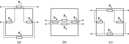
In general, four piezoresistors are used, as shown in following figure:

Arrangement a)
Gauges R2 and R4 are placed close to the centre of the membrane edges
- maximal stress in the direction perpendicular to the membrane edge
These resistors are oriented so that they sense the stress in the direction parallel to the current traversing them.
Resistors R1 and R3 are outside the membrane and thus they are not exposed to the stress related to the membrane deformation
- can be used for temperature compensation.
Arrangement b)
Same advantage in terms of the temperature compensation as the previous one.
Moreover, it shows up higher sensitivity because of two resistances placed in the centre of the membrane
where the stress is of the opposite sign comparing to the edges.
This fact will bring higher resistance variation in Wheatstone bridge arrangement.
Arrangement c)
Can be used when piezoresistors are made of silicon,
Gauges R2 and R4 are sensitive to the stress in the direction perpendicular to the membrane edge
and parallel to their current.
Two other gauges are placed to sense the stress perpendicular to their current flow.
Resistance change of the first two piezoresistors will always be opposite to that of the other two,
which leads to the increasing of the sensor sensitivity.
-
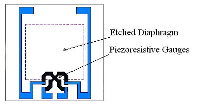
In another configuration, developed by Motorola, the Wheatstone bridge is replaced
by a cross-shaped piezoresistive element with four connections, as shown in following figure:


 Accelerometer


