 |
|
||
|
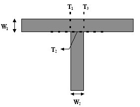
INTRODUCTION In microwave circuits T-branch discontinuity is found in "stub" matching configurations and filters, impedance networks, etc [1], [3]. In figure 1 is shown the general case of it.
Fig. 1 T-branch discontinuity The metallic traces after the branch (the horizontal segment of “T”) can have the same width with the vertical arm or can present different values. At the first look the T-branch seems to be a smaller discontinuity than the corner, for instance. One can be observed that from geometrical viewpoint the branch is created by two mirrored corners and the benefits seem to be a smaller excess capacitance (the lack of the sharped zone) and a smaller excess inductance. Because last years research activities have proved that usually right angle corners do not have large effects on signal tracks characteristic impedance if the field of application is not placed in microwave range, the natural conclusion will be the T-branch could be neglected. In reality a typical T-branch discontinuity (with all arms of equal width) represents a much stronger item than the corner. The first reason is that a branch in a trace generates an impedance mismatch on the order of about 50% and the second one is that usually the “duration” of this discontinuity is very long in comparison with corners or vias.
|
 Schematic design of PCB projects