 |
|
||
|
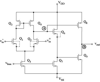
Improved uncompensated CMOS operational amplifier:
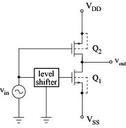
Increased output range
Q6 and Q7 act as the level shifter from the following schematics:
Approximate equivalent circuit of improved opamp:
Most of opamp applications use the feedback arrangement:
Cin ... overall capacitance of the input circuit including stray capacitances Input sine wave V(jw) amplified by: -AV(jw) Feedback signal:
Negative feedback in a low-frequency range Positive feedback in a high-frequency range Compensation:
Additional design step To prevent oscillation in feedback amplifiers
|
 Analogue filter


