Specific properties of a SC circuits: sampled-data system
- Signal passing through a switched capacitor is modulated by the clock frequency
Anti-aliasing filter is necessary in order to remove any components of input frequency above half of the clock frequency
- Output signal does not change continuously but in steps at the clock frequency
Another filter at the output may be used in order to remove aberrations caused by charge injected by the switches at the step transitions
- Input signal is sampled only once per clock cycle
Filter output deviates from the ideal one as the filter pole frequency approaches the clock frequency
It is recommended to keep the ratio of clock-to centre frequency as large as possible
(typically in range from 28:1 to 200:1)
SC circuits are often described by the z-transform
(instead the Laplace transform used in the case of continuous circuits)
SC resistors can be simulated by
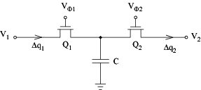
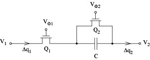
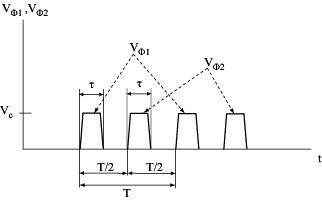
Clock waveforms:
Shunt SC integrator:
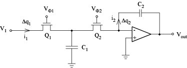
Series SC integrator:
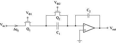
SC integrator simulates its active RC model well for signal frequencies w < 1/100T = fC/100
Related Reading
Gregorian, R., Temes G. C., Analog MOS integrated circuits for signal processing, Wiley, 1986.
Johns, D. A., Martin, K., Analog integrated circuit design, Wiley, 1997.
Razavi, B., RF Microelectronics, Prentice Hall, 1998.
Bendat, J. S., Piersol, A. G., Random Data: Analysis & Measurement Procedures, J. Wiley, 2000.

 Analogue filter


