IPCI logo
Internet-based Performance Centred Instruction
Analogue filters tutorial

Modules

1. Basic filter types and characteristics
2. Continuous time filters
3. Discrete time filters (switch-capacitor filters)

pages: [1] 2 | next

Discrete time filters (switch-capacitor filters)


o Characteristics of all active filters depend on the accuracy of their RC time constants

o Typical precision achieved for integrated resistors and capacitors is more than 10%

o Error of any RC time constant may be as large as 20%

o Ratio of capacitor values on a chip can be accurately controlled

o Switched capacitor filters use these capacitor ratios to achieve precision

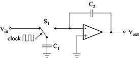
Key idea of Switch-Capacitor (SC) circuits:

Shown on the case of an integrator

  • Combination of C1 and the switch S1 simulates a resistor
  • Switch S1 toggles continuously at a clock frequency fC
  • Capacitor C1 charges to Vin when S1 is to the left
  • Charge from C1 is dumped into the integrator summing node when S1 is to the right
  • Charge on C1 during each clock cycle is

  • Average current transferred to the summing junction

  • Same effect as a resistor of value

  • Integrator cutoff frequency

  • Value of w0 can be controlled with great accuracy because the ratio of two capacitors on the same chip
    can be kept as small as 1%

  • Area needed by the simulated resistor is usually much smaller than that needed for a direct realization

  • Filter characteristics can be changed by changing fC

1. Basic filter types and characteristics
2. Continuous time filters
3. Discrete time filters (switch-capacitor filters)

pages: [1] 2 | next

go to top