 |
|
||
|
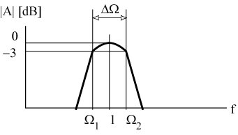
Passband characteristic:
W1 ... Lower -3 dB frequency W2 ... Upper -3 dB frequency DW = W2 - W1 ... Normalized bandwidth Wm = W2 W1 = 1 ... Normalized centre frequency (Q = 1)
Design of a band-pass filter
The simplest design Used commonly in wide-band filter applications
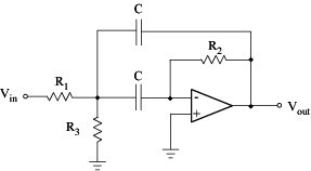
Different topologies and orders Used for narrow-band filters Second-order Band-pass Filter General transfer function for a second -order band-pass filter:
Corresponding transfer function:
By comparing the two preceding equations:
Centre frequency ...
Gain at fm ...
Filter quality ... Bandwidth ... MFB band-pass topology allows to adjust Q, Am, and fm independently
R3 ... does not affect bandwidth and gain ... can be used to modify the centre frequency
|
 Analogue filter

 ... Quality factor


